365328
A two Volts battery forward biases a diode however there is a drop of 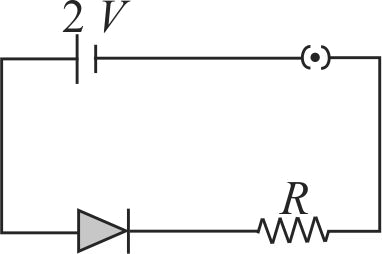
365328
A two Volts battery forward biases a diode however there is a drop of
365328
A two Volts battery forward biases a diode however there is a drop of
365328
A two Volts battery forward biases a diode however there is a drop of
365328
A two Volts battery forward biases a diode however there is a drop of