356031
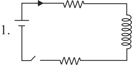
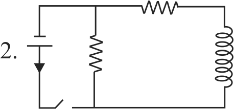
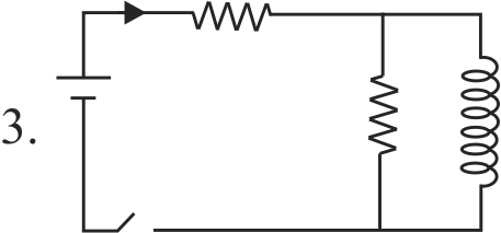
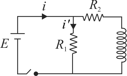
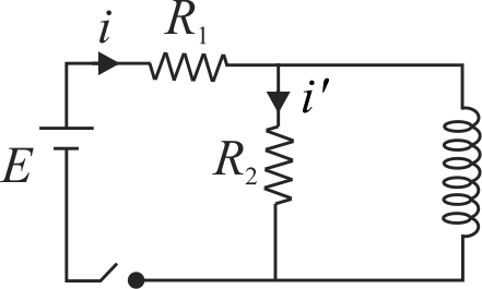
The figure shows three circuits with identical batteries, inductors and resistance. Rank the circuits according to the currents through the battery just after the switch is closed, greatest first.
1 \(i_{2}>i_{3}>i_{1}\)
2 \(i_{2}>i_{1}>i_{3}\)
3 \(i_{1}>i_{2}>i_{3}\)
4 \(i_{1}>i_{3}>i_{2}\)
Explanation:
In circuit (1), on closing the switch, the current in the inductor is zero due to selfinduction,\(i.e.\) \(i_{1}=0\). In circuit (2), on closing the switch, the current in the inductor is zero dut to self-induction. Therefore, \(i_{2}=i=\dfrac{E}{R_{1}}\) In circuit (3), on closing the switch, the current in the inductor is again zero due to the same reason. Therefore, \(i_{3}=i=\dfrac{E}{R_{1}+R_{2}}\) Thus, it is obvious that, \(i_{2}>i_{3}>i_{1}(=0)\).
AIIMS - 2007
PHXII07:ALTERNATING CURRENT
356032
A coil has resistance \(30\,ohm\) and inductive reactance \(20\,ohm\) at \(50\;Hz\) frequency. If an ac source, of \(200\,volt\), \(100\;Hz\), is connected across the coil, the current in the coil will be
1 \(4.0\;A\)
2 \(8.0\;A\)
3 \(7.2\;A\)
4 \(2.0\;A\)
Explanation:
If \(\omega=50 \times 2 \pi\) then \(\omega L = 20\,\Omega \) If \(\omega^{\prime}=100 \times 2 \pi\) then \({\omega ^\prime }L = 40\,\Omega \) Current flowing in the coil is \(I = \frac{{200}}{Z} = \frac{{200}}{{\sqrt {{R^2} + {{\left( {{\omega ^\prime }L} \right)}^2}} }} = 4\;A\)
PHXII07:ALTERNATING CURRENT
356033
Assertion : Average value of ac over a complete cycle is always zero. Reason : A choke coil consists of an inductor having some resistance R.
1 Both assertion and reason are correct and reason is the correct explanation of assertion.
2 Both assertion and reason are correct but reason is not the correct explanation of assertion.
3 Assertion is correct but reason is incorrect.
4 Assertion is incorrect but reason is correct.
Explanation:
The mean or average value of alternating current or e.m.f. during a full cycle is always equal to zero. So average value over a full cycle is always zero. Option (2) is correct.
PHXII07:ALTERNATING CURRENT
356034
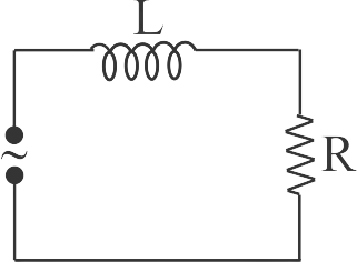
An inducer and a resistor in series are connected to an \(A.C\) supply of variable frequency. As the frequency of the source is increased, the phase angle between current and the potential difference across the circuit will:
1 first increase and then decrease
2 first decrease and then increase
3 go on decreasing
4 go on increasing
Explanation:
\(\tan \theta = \frac{{{X_L}}}{R} = \frac{{2\pi vL}}{R}\) As \(v\) increases \(\theta \) also increases.
PHXII07:ALTERNATING CURRENT
356035
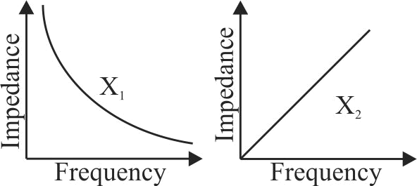
The graph given below depict the dependence of two reactive impedances \(X_{1}\) and \(X_{2}\) on the frequency of the alternating e.m.f. applied individually to them. We can then say that
1 \(X_{1}\) is an inductor and \(X_{2}\) is a capacitor
2 \(X_{1}\) is a resistor and \(X_{2}\) is a capacitor
3 \(X_{1}\) is a capacitor and \(X_{2}\) is an inductor
4 \(X_{1}\) is an inductor and \(X_{2}\) is a resistor
356031
The figure shows three circuits with identical batteries, inductors and resistance. Rank the circuits according to the currents through the battery just after the switch is closed, greatest first.
1 \(i_{2}>i_{3}>i_{1}\)
2 \(i_{2}>i_{1}>i_{3}\)
3 \(i_{1}>i_{2}>i_{3}\)
4 \(i_{1}>i_{3}>i_{2}\)
Explanation:
In circuit (1), on closing the switch, the current in the inductor is zero due to selfinduction,\(i.e.\) \(i_{1}=0\). In circuit (2), on closing the switch, the current in the inductor is zero dut to self-induction. Therefore, \(i_{2}=i=\dfrac{E}{R_{1}}\) In circuit (3), on closing the switch, the current in the inductor is again zero due to the same reason. Therefore, \(i_{3}=i=\dfrac{E}{R_{1}+R_{2}}\) Thus, it is obvious that, \(i_{2}>i_{3}>i_{1}(=0)\).
AIIMS - 2007
PHXII07:ALTERNATING CURRENT
356032
A coil has resistance \(30\,ohm\) and inductive reactance \(20\,ohm\) at \(50\;Hz\) frequency. If an ac source, of \(200\,volt\), \(100\;Hz\), is connected across the coil, the current in the coil will be
1 \(4.0\;A\)
2 \(8.0\;A\)
3 \(7.2\;A\)
4 \(2.0\;A\)
Explanation:
If \(\omega=50 \times 2 \pi\) then \(\omega L = 20\,\Omega \) If \(\omega^{\prime}=100 \times 2 \pi\) then \({\omega ^\prime }L = 40\,\Omega \) Current flowing in the coil is \(I = \frac{{200}}{Z} = \frac{{200}}{{\sqrt {{R^2} + {{\left( {{\omega ^\prime }L} \right)}^2}} }} = 4\;A\)
PHXII07:ALTERNATING CURRENT
356033
Assertion : Average value of ac over a complete cycle is always zero. Reason : A choke coil consists of an inductor having some resistance R.
1 Both assertion and reason are correct and reason is the correct explanation of assertion.
2 Both assertion and reason are correct but reason is not the correct explanation of assertion.
3 Assertion is correct but reason is incorrect.
4 Assertion is incorrect but reason is correct.
Explanation:
The mean or average value of alternating current or e.m.f. during a full cycle is always equal to zero. So average value over a full cycle is always zero. Option (2) is correct.
PHXII07:ALTERNATING CURRENT
356034
An inducer and a resistor in series are connected to an \(A.C\) supply of variable frequency. As the frequency of the source is increased, the phase angle between current and the potential difference across the circuit will:
1 first increase and then decrease
2 first decrease and then increase
3 go on decreasing
4 go on increasing
Explanation:
\(\tan \theta = \frac{{{X_L}}}{R} = \frac{{2\pi vL}}{R}\) As \(v\) increases \(\theta \) also increases.
PHXII07:ALTERNATING CURRENT
356035
The graph given below depict the dependence of two reactive impedances \(X_{1}\) and \(X_{2}\) on the frequency of the alternating e.m.f. applied individually to them. We can then say that
1 \(X_{1}\) is an inductor and \(X_{2}\) is a capacitor
2 \(X_{1}\) is a resistor and \(X_{2}\) is a capacitor
3 \(X_{1}\) is a capacitor and \(X_{2}\) is an inductor
4 \(X_{1}\) is an inductor and \(X_{2}\) is a resistor