359311
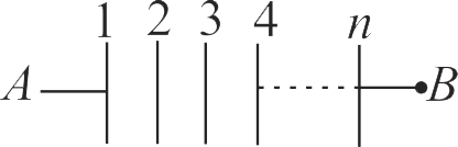
Find equivalent Capacitance between point \({A}\) and \({B}\) if Capacitance between any two plates is \({C}\).
1 \({\dfrac{C}{n+1}}\)
2 \({\dfrac{C}{2 n+1}}\)
3 \({\dfrac{C}{2 n-1}}\)
4 \({\dfrac{C}{n-1}}\)
Explanation:
There are total \({(n-1)}\) capacitors which are in series. So \({\dfrac{1}{C_{e q}}=\dfrac{1}{C}+\dfrac{1}{C}+\ldots(n-1)}\) times \(\begin{aligned}& \dfrac{1}{C_{e q}}=\dfrac{(n-1)}{C} \\& \Rightarrow C_{e q}=\dfrac{C}{n-1}\end{aligned}\)
PHXII02:ELECTROSTATIC POTENTIAL AND CAPACITANCE
359312
The ratio of the resultant capacities when three capacitors of \(2\mu F,\;4\mu F,{\rm{and}}\,6\mu F\;\) are connected first in series and then in parallel is
359313
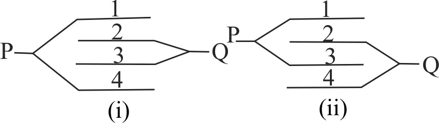
The following arrangement consists of four plates. The area of each plate is \(A\) and separation between successive plates is \(d\). The ratio of effective capacitance between \(P\) and \(Q\) as shown in figure (i) and (ii) is
1 \(\frac{2}{3}\)
2 \(\frac{3}{2}\)
3 \(\frac{4}{3}\)
4 \(1\)
Explanation:
For figure (i) The arrangement will work as a system of three capacitors connected in parallel as shown in the figure. The capacitance of each capactior,\(C = \frac{{{\varepsilon _0}A}}{d}\) The effective capacitance between P and Q is \({C_1} = 2\frac{{{\varepsilon _0}A}}{d}\) For figure (ii) The arrangement will work as two capacitors connected in parallel as shown in figure. The effective capacitance between P and Q is \({C_2} = \frac{{3{\varepsilon _0}A}}{d}\quad \therefore \frac{{C{}_1}}{{{C_2}}} = \frac{2}{3}\)
PHXII02:ELECTROSTATIC POTENTIAL AND CAPACITANCE
359314
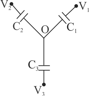
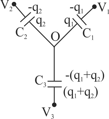
Three uncharged capacitors of capacitances \({C_1},{C_2}\,{\rm{and}}\,{C_3}\) are connected as shown in the figure. The potential at \(O\) will be:
Let \(V\) be the potential at the junction \(O\). There is an independent loop in the circuit. The total charge on the independent loop is zero i.e., (Charge \({C_1}\) ) + (Charge on \({C_2}\) ) = (Charge on \({C_3}\) ) \({q_1} + {q_2} = \left( {{q_1} + {q_2}} \right)\) \({C_1}\left( {V - {V_1}} \right) + {C_2}\left( {V - {V_2}} \right) = {C_3}\left( {{V_3} - V} \right)\) \( \Rightarrow V = \frac{{{C_1}{V_1} + {C_2}{V_2} + {C_3}{V_3}}}{{{C_1} + {C_2} + {C_2}}} = \frac{{\Sigma {V_i}{C_i}}}{{\Sigma {C_i}}}\)
PHXII02:ELECTROSTATIC POTENTIAL AND CAPACITANCE
359315
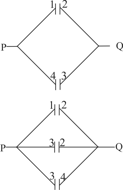
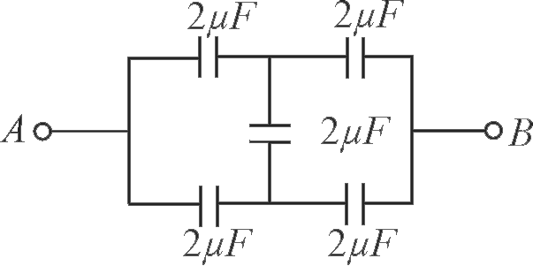
In the following circuit, the equivalent capacitance between terminal \({A}\) and terminal \({B}\) is:
1 \({2 \mu F}\)
2 \({1 \mu F}\)
3 \({0.5 \mu F}\)
4 \({4 \mu F}\)
Explanation:
Given circuit is balanced Wheatstone bridge so the middle capacitor can be disconnected. \({C_{AB}} = 1 + 1 = 2\mu F\)
359311
Find equivalent Capacitance between point \({A}\) and \({B}\) if Capacitance between any two plates is \({C}\).
1 \({\dfrac{C}{n+1}}\)
2 \({\dfrac{C}{2 n+1}}\)
3 \({\dfrac{C}{2 n-1}}\)
4 \({\dfrac{C}{n-1}}\)
Explanation:
There are total \({(n-1)}\) capacitors which are in series. So \({\dfrac{1}{C_{e q}}=\dfrac{1}{C}+\dfrac{1}{C}+\ldots(n-1)}\) times \(\begin{aligned}& \dfrac{1}{C_{e q}}=\dfrac{(n-1)}{C} \\& \Rightarrow C_{e q}=\dfrac{C}{n-1}\end{aligned}\)
PHXII02:ELECTROSTATIC POTENTIAL AND CAPACITANCE
359312
The ratio of the resultant capacities when three capacitors of \(2\mu F,\;4\mu F,{\rm{and}}\,6\mu F\;\) are connected first in series and then in parallel is
359313
The following arrangement consists of four plates. The area of each plate is \(A\) and separation between successive plates is \(d\). The ratio of effective capacitance between \(P\) and \(Q\) as shown in figure (i) and (ii) is
1 \(\frac{2}{3}\)
2 \(\frac{3}{2}\)
3 \(\frac{4}{3}\)
4 \(1\)
Explanation:
For figure (i) The arrangement will work as a system of three capacitors connected in parallel as shown in the figure. The capacitance of each capactior,\(C = \frac{{{\varepsilon _0}A}}{d}\) The effective capacitance between P and Q is \({C_1} = 2\frac{{{\varepsilon _0}A}}{d}\) For figure (ii) The arrangement will work as two capacitors connected in parallel as shown in figure. The effective capacitance between P and Q is \({C_2} = \frac{{3{\varepsilon _0}A}}{d}\quad \therefore \frac{{C{}_1}}{{{C_2}}} = \frac{2}{3}\)
PHXII02:ELECTROSTATIC POTENTIAL AND CAPACITANCE
359314
Three uncharged capacitors of capacitances \({C_1},{C_2}\,{\rm{and}}\,{C_3}\) are connected as shown in the figure. The potential at \(O\) will be:
Let \(V\) be the potential at the junction \(O\). There is an independent loop in the circuit. The total charge on the independent loop is zero i.e., (Charge \({C_1}\) ) + (Charge on \({C_2}\) ) = (Charge on \({C_3}\) ) \({q_1} + {q_2} = \left( {{q_1} + {q_2}} \right)\) \({C_1}\left( {V - {V_1}} \right) + {C_2}\left( {V - {V_2}} \right) = {C_3}\left( {{V_3} - V} \right)\) \( \Rightarrow V = \frac{{{C_1}{V_1} + {C_2}{V_2} + {C_3}{V_3}}}{{{C_1} + {C_2} + {C_2}}} = \frac{{\Sigma {V_i}{C_i}}}{{\Sigma {C_i}}}\)
PHXII02:ELECTROSTATIC POTENTIAL AND CAPACITANCE
359315
In the following circuit, the equivalent capacitance between terminal \({A}\) and terminal \({B}\) is:
1 \({2 \mu F}\)
2 \({1 \mu F}\)
3 \({0.5 \mu F}\)
4 \({4 \mu F}\)
Explanation:
Given circuit is balanced Wheatstone bridge so the middle capacitor can be disconnected. \({C_{AB}} = 1 + 1 = 2\mu F\)
NEET Test Series from KOTA - 10 Papers In MS WORD
WhatsApp Here
PHXII02:ELECTROSTATIC POTENTIAL AND CAPACITANCE
359311
Find equivalent Capacitance between point \({A}\) and \({B}\) if Capacitance between any two plates is \({C}\).
1 \({\dfrac{C}{n+1}}\)
2 \({\dfrac{C}{2 n+1}}\)
3 \({\dfrac{C}{2 n-1}}\)
4 \({\dfrac{C}{n-1}}\)
Explanation:
There are total \({(n-1)}\) capacitors which are in series. So \({\dfrac{1}{C_{e q}}=\dfrac{1}{C}+\dfrac{1}{C}+\ldots(n-1)}\) times \(\begin{aligned}& \dfrac{1}{C_{e q}}=\dfrac{(n-1)}{C} \\& \Rightarrow C_{e q}=\dfrac{C}{n-1}\end{aligned}\)
PHXII02:ELECTROSTATIC POTENTIAL AND CAPACITANCE
359312
The ratio of the resultant capacities when three capacitors of \(2\mu F,\;4\mu F,{\rm{and}}\,6\mu F\;\) are connected first in series and then in parallel is
359313
The following arrangement consists of four plates. The area of each plate is \(A\) and separation between successive plates is \(d\). The ratio of effective capacitance between \(P\) and \(Q\) as shown in figure (i) and (ii) is
1 \(\frac{2}{3}\)
2 \(\frac{3}{2}\)
3 \(\frac{4}{3}\)
4 \(1\)
Explanation:
For figure (i) The arrangement will work as a system of three capacitors connected in parallel as shown in the figure. The capacitance of each capactior,\(C = \frac{{{\varepsilon _0}A}}{d}\) The effective capacitance between P and Q is \({C_1} = 2\frac{{{\varepsilon _0}A}}{d}\) For figure (ii) The arrangement will work as two capacitors connected in parallel as shown in figure. The effective capacitance between P and Q is \({C_2} = \frac{{3{\varepsilon _0}A}}{d}\quad \therefore \frac{{C{}_1}}{{{C_2}}} = \frac{2}{3}\)
PHXII02:ELECTROSTATIC POTENTIAL AND CAPACITANCE
359314
Three uncharged capacitors of capacitances \({C_1},{C_2}\,{\rm{and}}\,{C_3}\) are connected as shown in the figure. The potential at \(O\) will be:
Let \(V\) be the potential at the junction \(O\). There is an independent loop in the circuit. The total charge on the independent loop is zero i.e., (Charge \({C_1}\) ) + (Charge on \({C_2}\) ) = (Charge on \({C_3}\) ) \({q_1} + {q_2} = \left( {{q_1} + {q_2}} \right)\) \({C_1}\left( {V - {V_1}} \right) + {C_2}\left( {V - {V_2}} \right) = {C_3}\left( {{V_3} - V} \right)\) \( \Rightarrow V = \frac{{{C_1}{V_1} + {C_2}{V_2} + {C_3}{V_3}}}{{{C_1} + {C_2} + {C_2}}} = \frac{{\Sigma {V_i}{C_i}}}{{\Sigma {C_i}}}\)
PHXII02:ELECTROSTATIC POTENTIAL AND CAPACITANCE
359315
In the following circuit, the equivalent capacitance between terminal \({A}\) and terminal \({B}\) is:
1 \({2 \mu F}\)
2 \({1 \mu F}\)
3 \({0.5 \mu F}\)
4 \({4 \mu F}\)
Explanation:
Given circuit is balanced Wheatstone bridge so the middle capacitor can be disconnected. \({C_{AB}} = 1 + 1 = 2\mu F\)