PHXII14:SEMICONDUCTOR ELECTRONICS- MATERIALS- DEVICES AND SIMPLE CIRCUITS
365482
The input characteristics of a transistor in \(CE\) mode is the graph obtained by plotting
1 \({I_B}\) aganist \({V_{CE}}\) at constant \({V_{BE}}\)
2 \({I_B}\) aganist \({I_C}\) at constant \({V_{BE}}\)
3 \({I_B}\) aganist \({V_{BE}}\) at constant \({V_{CE}}\)
4 \({I_B}\) aganist \({I_C}\) at constant \({V_{CE}}\)
Explanation:
The input characteristics of a transistor in \(CE\) mode is the graph obtained by plotting base current \({I_B}\) aganist base - emitter voltage \({V_{BE}}\) at constant collector - emitter voltage \({V_{CE}}\).
KCET - 2015
PHXII14:SEMICONDUCTOR ELECTRONICS- MATERIALS- DEVICES AND SIMPLE CIRCUITS
365483
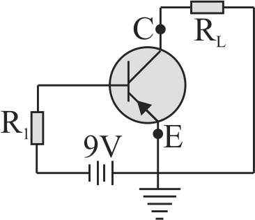
In the circuit shown, the base current is \(30\,\mu A.\) The value of \({R_1}\) is
PHXII14:SEMICONDUCTOR ELECTRONICS- MATERIALS- DEVICES AND SIMPLE CIRCUITS
365484
In the case of constant \(\alpha\) and \(\beta\) of a transistor.
1 \(\alpha \beta=1\)
2 \(\beta>1, \alpha < 1\)
3 \(\alpha=\beta\)
4 \(\beta < 1, \alpha>1\)
Explanation:
In case of transistor, constant \(\alpha\) is current gain in common base configuration and constant \(\beta\) is current gain in common emitter configuration. We know: \(\alpha=\dfrac{\Delta I_{C}}{\Delta I_{E}} \simeq \dfrac{I_{C}}{I_{E}}, \beta=\dfrac{\Delta I_{C}}{\Delta I_{B}} \simeq \dfrac{I_{C}}{I_{B}}\) Typical values of currents are \(I_{C} \approx 15 m A\), \({I_B} \approx 7.5\,\mu A,{I_E} = 25\;mA\) \(\Rightarrow \alpha < 1, \beta>1\)
AIIMS - 2013
PHXII14:SEMICONDUCTOR ELECTRONICS- MATERIALS- DEVICES AND SIMPLE CIRCUITS
365485
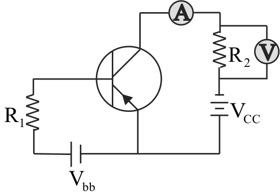
If the resistance \({R_1}\) is increased, how will the readings of the ammeter and voltmeter change?
1 Both increases
2 Both decreases
3 Ammeter increases & voltmeter decreases
4 Ammeter decreases & voltmeter increases
Explanation:
\({I_B} = \frac{{{V_{BB}} - {V_{BE}}}}{{{R_1}}}.\) If \({R_1}\) is increased,\({I_B}\) will decrease. Since \({I_C} = \beta {I_B},\) it will result in decrease in \({I_C}.\)
NEET Test Series from KOTA - 10 Papers In MS WORD
WhatsApp Here
PHXII14:SEMICONDUCTOR ELECTRONICS- MATERIALS- DEVICES AND SIMPLE CIRCUITS
365482
The input characteristics of a transistor in \(CE\) mode is the graph obtained by plotting
1 \({I_B}\) aganist \({V_{CE}}\) at constant \({V_{BE}}\)
2 \({I_B}\) aganist \({I_C}\) at constant \({V_{BE}}\)
3 \({I_B}\) aganist \({V_{BE}}\) at constant \({V_{CE}}\)
4 \({I_B}\) aganist \({I_C}\) at constant \({V_{CE}}\)
Explanation:
The input characteristics of a transistor in \(CE\) mode is the graph obtained by plotting base current \({I_B}\) aganist base - emitter voltage \({V_{BE}}\) at constant collector - emitter voltage \({V_{CE}}\).
KCET - 2015
PHXII14:SEMICONDUCTOR ELECTRONICS- MATERIALS- DEVICES AND SIMPLE CIRCUITS
365483
In the circuit shown, the base current is \(30\,\mu A.\) The value of \({R_1}\) is
PHXII14:SEMICONDUCTOR ELECTRONICS- MATERIALS- DEVICES AND SIMPLE CIRCUITS
365484
In the case of constant \(\alpha\) and \(\beta\) of a transistor.
1 \(\alpha \beta=1\)
2 \(\beta>1, \alpha < 1\)
3 \(\alpha=\beta\)
4 \(\beta < 1, \alpha>1\)
Explanation:
In case of transistor, constant \(\alpha\) is current gain in common base configuration and constant \(\beta\) is current gain in common emitter configuration. We know: \(\alpha=\dfrac{\Delta I_{C}}{\Delta I_{E}} \simeq \dfrac{I_{C}}{I_{E}}, \beta=\dfrac{\Delta I_{C}}{\Delta I_{B}} \simeq \dfrac{I_{C}}{I_{B}}\) Typical values of currents are \(I_{C} \approx 15 m A\), \({I_B} \approx 7.5\,\mu A,{I_E} = 25\;mA\) \(\Rightarrow \alpha < 1, \beta>1\)
AIIMS - 2013
PHXII14:SEMICONDUCTOR ELECTRONICS- MATERIALS- DEVICES AND SIMPLE CIRCUITS
365485
If the resistance \({R_1}\) is increased, how will the readings of the ammeter and voltmeter change?
1 Both increases
2 Both decreases
3 Ammeter increases & voltmeter decreases
4 Ammeter decreases & voltmeter increases
Explanation:
\({I_B} = \frac{{{V_{BB}} - {V_{BE}}}}{{{R_1}}}.\) If \({R_1}\) is increased,\({I_B}\) will decrease. Since \({I_C} = \beta {I_B},\) it will result in decrease in \({I_C}.\)
PHXII14:SEMICONDUCTOR ELECTRONICS- MATERIALS- DEVICES AND SIMPLE CIRCUITS
365482
The input characteristics of a transistor in \(CE\) mode is the graph obtained by plotting
1 \({I_B}\) aganist \({V_{CE}}\) at constant \({V_{BE}}\)
2 \({I_B}\) aganist \({I_C}\) at constant \({V_{BE}}\)
3 \({I_B}\) aganist \({V_{BE}}\) at constant \({V_{CE}}\)
4 \({I_B}\) aganist \({I_C}\) at constant \({V_{CE}}\)
Explanation:
The input characteristics of a transistor in \(CE\) mode is the graph obtained by plotting base current \({I_B}\) aganist base - emitter voltage \({V_{BE}}\) at constant collector - emitter voltage \({V_{CE}}\).
KCET - 2015
PHXII14:SEMICONDUCTOR ELECTRONICS- MATERIALS- DEVICES AND SIMPLE CIRCUITS
365483
In the circuit shown, the base current is \(30\,\mu A.\) The value of \({R_1}\) is
PHXII14:SEMICONDUCTOR ELECTRONICS- MATERIALS- DEVICES AND SIMPLE CIRCUITS
365484
In the case of constant \(\alpha\) and \(\beta\) of a transistor.
1 \(\alpha \beta=1\)
2 \(\beta>1, \alpha < 1\)
3 \(\alpha=\beta\)
4 \(\beta < 1, \alpha>1\)
Explanation:
In case of transistor, constant \(\alpha\) is current gain in common base configuration and constant \(\beta\) is current gain in common emitter configuration. We know: \(\alpha=\dfrac{\Delta I_{C}}{\Delta I_{E}} \simeq \dfrac{I_{C}}{I_{E}}, \beta=\dfrac{\Delta I_{C}}{\Delta I_{B}} \simeq \dfrac{I_{C}}{I_{B}}\) Typical values of currents are \(I_{C} \approx 15 m A\), \({I_B} \approx 7.5\,\mu A,{I_E} = 25\;mA\) \(\Rightarrow \alpha < 1, \beta>1\)
AIIMS - 2013
PHXII14:SEMICONDUCTOR ELECTRONICS- MATERIALS- DEVICES AND SIMPLE CIRCUITS
365485
If the resistance \({R_1}\) is increased, how will the readings of the ammeter and voltmeter change?
1 Both increases
2 Both decreases
3 Ammeter increases & voltmeter decreases
4 Ammeter decreases & voltmeter increases
Explanation:
\({I_B} = \frac{{{V_{BB}} - {V_{BE}}}}{{{R_1}}}.\) If \({R_1}\) is increased,\({I_B}\) will decrease. Since \({I_C} = \beta {I_B},\) it will result in decrease in \({I_C}.\)