NEET Test Series from KOTA - 10 Papers In MS WORD
WhatsApp Here
PHXII03:CURRENT ELECTRICITY
357495
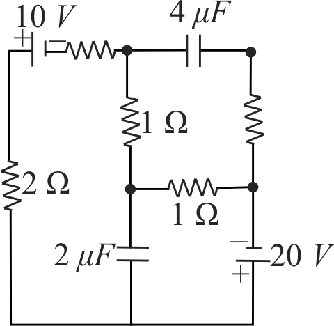
In the figure shown find ratio of charges on \({4 \mu {F}}\) and \({2 \mu {F}}\) Capacitors in steady state.
1 3.56
2 4.44
3 7.63
4 9.45
Explanation:
In the given circuit we circulate currents \(I_{1}\) in the single loops as shown in figure. As we know that in steady state no current flows through the branch of capacitor so we do not consider any current in the branches in which capacitors are connected as shown. Current in the single loop, \(I=\dfrac{10}{5}=2 {~A}\) For potential drop from \(A\) to \(B\),\(V_{A}-(2)-(2)=V_{B} \Rightarrow V_{A}-V_{B}=4 {~V}\) For potential drop from \(C\) to \(D\),\(V_{C}-(2)+20=V_{D} \Rightarrow V_{A}-V_{B}=18 {~V}\) Charge on capacitors. \(q_{4 \mu F}=C V\) and \(q_{2 \mu F}=C V_{C D}\) \(\Rightarrow q_{2 \mu {F}}=2 \times 18=36 \mu {C}\) \( \Rightarrow \frac{{{q_{{\rm{4}}\mu {\rm{F}}}}}}{{{q_{2\mu {\rm{F}}}}}} = \frac{{16}}{{36}} = \frac{4}{9} = 4.44\)
PHXII03:CURRENT ELECTRICITY
357496
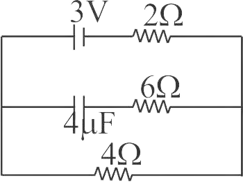
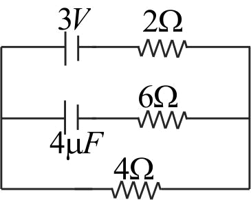
Find the potential drop across \(4\mu F\) capacitor and \(6\Omega \) resistor in figure
1 \(0.3\,V\)
2 \(0.2\,V\)
3 \(0,0\)
4 \(2V,0\)
Explanation:
At steady state condition. \(I = \frac{3}{{2 + 4}} = \frac{1}{2}A\) Potential drop across \(4\Omega \) resistor is \(V = 4 \times \frac{1}{2} = 2V\) The whole potential drop occurs across \(4\mu F\) capacitor as current does not flow through the branch containing capacitor. The potential difference across \(6{\kern 1pt} \Omega \) resistor is zero.
PHXII03:CURRENT ELECTRICITY
357497
Assertion : The switch \(S\) shown in the figure is closed at \(t=0\). Initial current flowing through battery is \(\frac{E}{{R + r}}\) Reason : Initially capacitor was uncharged, so resistance offered by capacitor at \(t = 0\) is zero.
1 Both Assertion and Reason are correct and Reason is the correct explanation of the Assertion.
2 Both Assertion and Reason are correct but Reason is not the correct explanation of the Assertion.
3 Assertion is correct but Reason is incorrect.
4 Assertion is incorrect but reason is correct.
Explanation:
Charge on capacitor \(q=C E\left(1-e^{-t l C R_{e q}}\right)\)\(\therefore I=\dfrac{d q}{d t}=\dfrac{E}{R_{e q}} e^{-t l C R}\)At \(t=0\) (switch closed)\(I=\dfrac{E}{R_{e q}}=\dfrac{E}{R+r} \Rightarrow\) resistance offered by capacitor is zeroSo correct option is (1).
PHXII03:CURRENT ELECTRICITY
357498
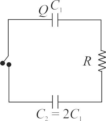
Two capacitors \({C_1}\) and \({C_2} = 2{C_1}\) are connected in a circuit with a switch between them as shown in the figure. Initially the switch is open and \({C_1}\) holds charge \(Q\). The switch is closed. At steady state, the charge on each capacitor will be
1 \(Q,2Q\)
2 \(\frac{Q}{3},\frac{{2Q}}{3}\)
3 \(\dfrac{3 Q}{2}, 3 \mathrm{Q}\)
4 \(\frac{{2Q}}{3},\frac{{4Q}}{3}\)
Explanation:
In steady state, both the capacitors are at the same potential, \(i.e.,\) \(\frac{{{Q_1}}}{{{C_1}}} = \frac{{{Q_2}}}{{{C_2}}}\) or \(\frac{{{Q_1}}}{C} = \frac{{{Q_2}}}{{2\,C}}\) or \({Q_2} = 2\,{Q_1}\) Also \(Q_{1}+Q_{2}=Q\) \(\therefore {Q_1} = \frac{Q}{3},{Q_2} = \frac{{2Q}}{3}\)
357495
In the figure shown find ratio of charges on \({4 \mu {F}}\) and \({2 \mu {F}}\) Capacitors in steady state.
1 3.56
2 4.44
3 7.63
4 9.45
Explanation:
In the given circuit we circulate currents \(I_{1}\) in the single loops as shown in figure. As we know that in steady state no current flows through the branch of capacitor so we do not consider any current in the branches in which capacitors are connected as shown. Current in the single loop, \(I=\dfrac{10}{5}=2 {~A}\) For potential drop from \(A\) to \(B\),\(V_{A}-(2)-(2)=V_{B} \Rightarrow V_{A}-V_{B}=4 {~V}\) For potential drop from \(C\) to \(D\),\(V_{C}-(2)+20=V_{D} \Rightarrow V_{A}-V_{B}=18 {~V}\) Charge on capacitors. \(q_{4 \mu F}=C V\) and \(q_{2 \mu F}=C V_{C D}\) \(\Rightarrow q_{2 \mu {F}}=2 \times 18=36 \mu {C}\) \( \Rightarrow \frac{{{q_{{\rm{4}}\mu {\rm{F}}}}}}{{{q_{2\mu {\rm{F}}}}}} = \frac{{16}}{{36}} = \frac{4}{9} = 4.44\)
PHXII03:CURRENT ELECTRICITY
357496
Find the potential drop across \(4\mu F\) capacitor and \(6\Omega \) resistor in figure
1 \(0.3\,V\)
2 \(0.2\,V\)
3 \(0,0\)
4 \(2V,0\)
Explanation:
At steady state condition. \(I = \frac{3}{{2 + 4}} = \frac{1}{2}A\) Potential drop across \(4\Omega \) resistor is \(V = 4 \times \frac{1}{2} = 2V\) The whole potential drop occurs across \(4\mu F\) capacitor as current does not flow through the branch containing capacitor. The potential difference across \(6{\kern 1pt} \Omega \) resistor is zero.
PHXII03:CURRENT ELECTRICITY
357497
Assertion : The switch \(S\) shown in the figure is closed at \(t=0\). Initial current flowing through battery is \(\frac{E}{{R + r}}\) Reason : Initially capacitor was uncharged, so resistance offered by capacitor at \(t = 0\) is zero.
1 Both Assertion and Reason are correct and Reason is the correct explanation of the Assertion.
2 Both Assertion and Reason are correct but Reason is not the correct explanation of the Assertion.
3 Assertion is correct but Reason is incorrect.
4 Assertion is incorrect but reason is correct.
Explanation:
Charge on capacitor \(q=C E\left(1-e^{-t l C R_{e q}}\right)\)\(\therefore I=\dfrac{d q}{d t}=\dfrac{E}{R_{e q}} e^{-t l C R}\)At \(t=0\) (switch closed)\(I=\dfrac{E}{R_{e q}}=\dfrac{E}{R+r} \Rightarrow\) resistance offered by capacitor is zeroSo correct option is (1).
PHXII03:CURRENT ELECTRICITY
357498
Two capacitors \({C_1}\) and \({C_2} = 2{C_1}\) are connected in a circuit with a switch between them as shown in the figure. Initially the switch is open and \({C_1}\) holds charge \(Q\). The switch is closed. At steady state, the charge on each capacitor will be
1 \(Q,2Q\)
2 \(\frac{Q}{3},\frac{{2Q}}{3}\)
3 \(\dfrac{3 Q}{2}, 3 \mathrm{Q}\)
4 \(\frac{{2Q}}{3},\frac{{4Q}}{3}\)
Explanation:
In steady state, both the capacitors are at the same potential, \(i.e.,\) \(\frac{{{Q_1}}}{{{C_1}}} = \frac{{{Q_2}}}{{{C_2}}}\) or \(\frac{{{Q_1}}}{C} = \frac{{{Q_2}}}{{2\,C}}\) or \({Q_2} = 2\,{Q_1}\) Also \(Q_{1}+Q_{2}=Q\) \(\therefore {Q_1} = \frac{Q}{3},{Q_2} = \frac{{2Q}}{3}\)