NEET Test Series from KOTA - 10 Papers In MS WORD
WhatsApp Here
PHXII03:CURRENT ELECTRICITY
357486
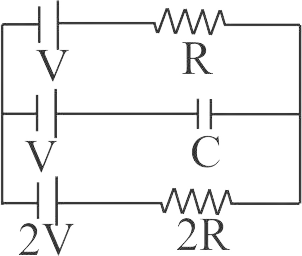
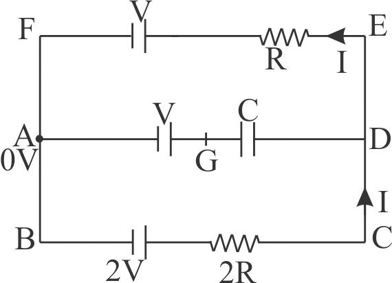
In the circuit shown in figure, with steady current, the potential drop across the capacitor must be
1 \(\frac{{2V}}{3}\)
2 \(\frac{V}{2}\)
3 \(V\)
4 \(\frac{V}{3}\)
Explanation:
Applying Kirchhoff’s law in \(BCDEFAB\) we get, \(I = \frac{V}{{3R}}\) Let \(A\) be at 0 \(V\). Then potential at \(G\) is \(V\). Applying Krichhoff’s law for \(AFED\), we get \(0 + V + IR = {V_D}\) \( \Rightarrow 0 + V + \frac{V}{{3R}} \times R = {V_D} \Rightarrow {V_D} = \frac{{4V}}{3}\) \({V_D} - {V_G} = \frac{V}{3}\)
PHXII03:CURRENT ELECTRICITY
357487
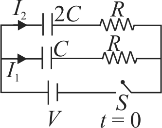
In the circuit shown switch is closed at time \(t=0\). Let \(I_{1}\) and \(I_{2}\) be the currents in both branches at \(t=0\), then ratio of \(\dfrac{I_{1}}{I_{2}}\).
1 \(\dfrac{I_{1}}{I_{2}}=2: 1\)
2 \(=1: 2\)
3 \(\dfrac{I_{1}}{I_{2}}=1: 1\)
4 \(\dfrac{I_{1}}{I_{2}}=\dfrac{2 R C}{R C}\)
Explanation:
At \(t=0\) capacitors can be replaced with conducting wires and hence current in both branches \(I=\dfrac{V}{R}\). \(\Rightarrow \dfrac{I_{1}}{I_{2}}=1: 1\)
PHXII03:CURRENT ELECTRICITY
357488
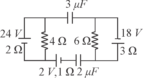
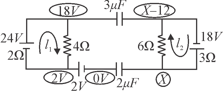
Calculate the charge on capacitor \({A}\) in the circuit shown in figure in steady state.
1 \(16\,\mu C\)
2 \(36\,\mu C\)
3 \(54\,\mu C\)
4 \(72\,\mu C\)
Explanation:
The current distribution is shown in figure. As we know that in steady state no current will flow in the two branches consisting of capacitors. From figure the currents in the two loops are given as \(i_{1}=\dfrac{24}{4+2}=4 {~A} \text { and } i_{2}=\dfrac{18}{3+6}=2 {~A}\) In the figure we consider a potential \({x}\) at the right plate of the \(2\,mF\) capacitor and zero at the left plate of this capacitor and find the potentials at the plates of other capacitor as shown in the figure. Now writing nodal equation for unknown potential \({x}\), we have \(\begin{array}{ll} & 2 x+3(x-12-18)=0 \\\Rightarrow \quad & 5 x=90 \\\Rightarrow \quad & x=18 {~V}\end{array}\) Charge on \(2\,\mu F\) capacitor is given as \({q_{2\mu F}} = 2 \times 18 = 36\,\mu C\) Charge on \(3\,\mu F\) capacitor is given as \({q_{3\mu F}} = 3 \times (18 - 6) = 36\,\mu C\)
PHXII03:CURRENT ELECTRICITY
357489
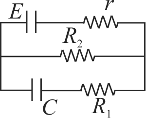
In the given figure each plate of capacitance \(C\) has value of charge -
1 \(C E\)
2 \(\dfrac{C E R_{1}}{R_{2}-r}\)
3 \(\dfrac{C E R_{2}}{R_{2}+r}\)
4 \(\dfrac{C E R_{1}}{R_{1}-r}\)
Explanation:
\(I=\dfrac{E}{r+R_{2}} P . D \operatorname{across} R_{2}=I R_{2}=\dfrac{E R_{2}}{r+R_{2}}\) \(Q=\dfrac{C E R_{2}}{r+R_{2}}\)
357486
In the circuit shown in figure, with steady current, the potential drop across the capacitor must be
1 \(\frac{{2V}}{3}\)
2 \(\frac{V}{2}\)
3 \(V\)
4 \(\frac{V}{3}\)
Explanation:
Applying Kirchhoff’s law in \(BCDEFAB\) we get, \(I = \frac{V}{{3R}}\) Let \(A\) be at 0 \(V\). Then potential at \(G\) is \(V\). Applying Krichhoff’s law for \(AFED\), we get \(0 + V + IR = {V_D}\) \( \Rightarrow 0 + V + \frac{V}{{3R}} \times R = {V_D} \Rightarrow {V_D} = \frac{{4V}}{3}\) \({V_D} - {V_G} = \frac{V}{3}\)
PHXII03:CURRENT ELECTRICITY
357487
In the circuit shown switch is closed at time \(t=0\). Let \(I_{1}\) and \(I_{2}\) be the currents in both branches at \(t=0\), then ratio of \(\dfrac{I_{1}}{I_{2}}\).
1 \(\dfrac{I_{1}}{I_{2}}=2: 1\)
2 \(=1: 2\)
3 \(\dfrac{I_{1}}{I_{2}}=1: 1\)
4 \(\dfrac{I_{1}}{I_{2}}=\dfrac{2 R C}{R C}\)
Explanation:
At \(t=0\) capacitors can be replaced with conducting wires and hence current in both branches \(I=\dfrac{V}{R}\). \(\Rightarrow \dfrac{I_{1}}{I_{2}}=1: 1\)
PHXII03:CURRENT ELECTRICITY
357488
Calculate the charge on capacitor \({A}\) in the circuit shown in figure in steady state.
1 \(16\,\mu C\)
2 \(36\,\mu C\)
3 \(54\,\mu C\)
4 \(72\,\mu C\)
Explanation:
The current distribution is shown in figure. As we know that in steady state no current will flow in the two branches consisting of capacitors. From figure the currents in the two loops are given as \(i_{1}=\dfrac{24}{4+2}=4 {~A} \text { and } i_{2}=\dfrac{18}{3+6}=2 {~A}\) In the figure we consider a potential \({x}\) at the right plate of the \(2\,mF\) capacitor and zero at the left plate of this capacitor and find the potentials at the plates of other capacitor as shown in the figure. Now writing nodal equation for unknown potential \({x}\), we have \(\begin{array}{ll} & 2 x+3(x-12-18)=0 \\\Rightarrow \quad & 5 x=90 \\\Rightarrow \quad & x=18 {~V}\end{array}\) Charge on \(2\,\mu F\) capacitor is given as \({q_{2\mu F}} = 2 \times 18 = 36\,\mu C\) Charge on \(3\,\mu F\) capacitor is given as \({q_{3\mu F}} = 3 \times (18 - 6) = 36\,\mu C\)
PHXII03:CURRENT ELECTRICITY
357489
In the given figure each plate of capacitance \(C\) has value of charge -
1 \(C E\)
2 \(\dfrac{C E R_{1}}{R_{2}-r}\)
3 \(\dfrac{C E R_{2}}{R_{2}+r}\)
4 \(\dfrac{C E R_{1}}{R_{1}-r}\)
Explanation:
\(I=\dfrac{E}{r+R_{2}} P . D \operatorname{across} R_{2}=I R_{2}=\dfrac{E R_{2}}{r+R_{2}}\) \(Q=\dfrac{C E R_{2}}{r+R_{2}}\)