357482
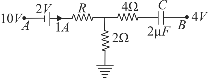
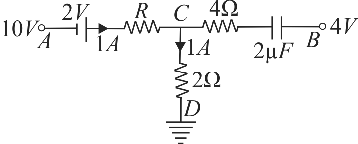
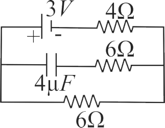
A network of resistances, cell and capacitor is shown in figure. In steady state condition, the charge on capacitor is , while is unknown resistance. Values of and are respectively
1 and
2 and
3 and
4 and
Explanation:
In the steady state, capacitor acts as a open circuit, hence no current will flow through . The currents distribution is shown in figure. The potential difference between and is As ( is earthed) The potential drop across the resistance Resistance, As there is no current in , so there is no potential drop across it. The potential drop across the capacitor The charge on the capacitor is
PHXII03:CURRENT ELECTRICITY
357483
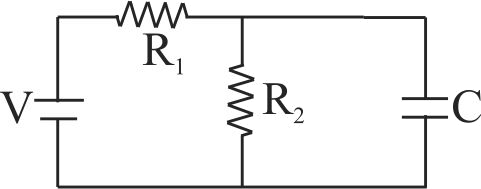
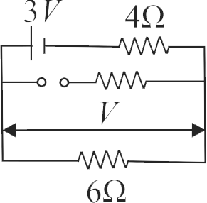
In the circuit shown in the figure, the steady state voltage drop across the capacitor is . Then
1
2
3
4
Explanation:
In the steady state no current will flow in the branch containing the capacitor. { and are in parallel } Hence However, the potential across the capacitor will be equal to the potential difference across the resistor
PHXII03:CURRENT ELECTRICITY
357484
A capacitor of is connected as shown in the circuit. The internal resistance of the battery is . The amount of charges on the capacitor will be
1
2
3
4
Explanation:
No current is allowed to flow through resistance because of capacitor. The current drawn by resistance. Terminal potential difference of battery, Charge on capacitor plates,
PHXII03:CURRENT ELECTRICITY
357485
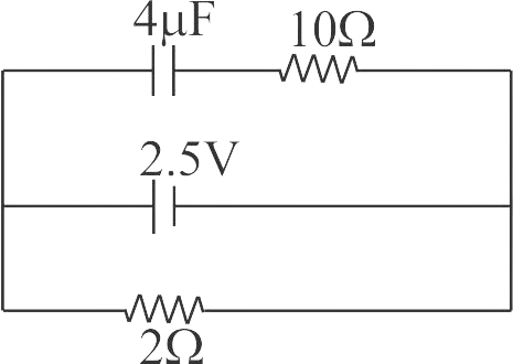
In the network shown below, the charge accumulated in the capacitor in steady state will be
1
2
3
4
Explanation:
Steady state of capacitor when there is no current flowing through it, the capacitor will behave as an open circuit. The equivalent circuit diagram is given by, (As there is no current following through the capacitor and resistor) Current flowing through the circuit is given by, . Voltage across resistor and capacitor is same, as shown in the diagram The charge accumulated in capacitor in its steady state is,
NEET Test Series from KOTA - 10 Papers In MS WORD
WhatsApp Here
PHXII03:CURRENT ELECTRICITY
357482
A network of resistances, cell and capacitor is shown in figure. In steady state condition, the charge on capacitor is , while is unknown resistance. Values of and are respectively
1 and
2 and
3 and
4 and
Explanation:
In the steady state, capacitor acts as a open circuit, hence no current will flow through . The currents distribution is shown in figure. The potential difference between and is As ( is earthed) The potential drop across the resistance Resistance, As there is no current in , so there is no potential drop across it. The potential drop across the capacitor The charge on the capacitor is
PHXII03:CURRENT ELECTRICITY
357483
In the circuit shown in the figure, the steady state voltage drop across the capacitor is . Then
1
2
3
4
Explanation:
In the steady state no current will flow in the branch containing the capacitor. { and are in parallel } Hence However, the potential across the capacitor will be equal to the potential difference across the resistor
PHXII03:CURRENT ELECTRICITY
357484
A capacitor of is connected as shown in the circuit. The internal resistance of the battery is . The amount of charges on the capacitor will be
1
2
3
4
Explanation:
No current is allowed to flow through resistance because of capacitor. The current drawn by resistance. Terminal potential difference of battery, Charge on capacitor plates,
PHXII03:CURRENT ELECTRICITY
357485
In the network shown below, the charge accumulated in the capacitor in steady state will be
1
2
3
4
Explanation:
Steady state of capacitor when there is no current flowing through it, the capacitor will behave as an open circuit. The equivalent circuit diagram is given by, (As there is no current following through the capacitor and resistor) Current flowing through the circuit is given by, . Voltage across resistor and capacitor is same, as shown in the diagram The charge accumulated in capacitor in its steady state is,