166010
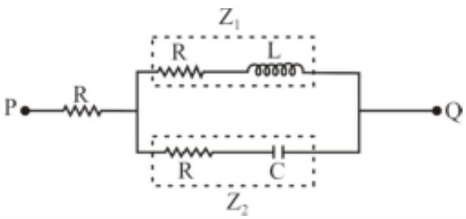
A voltage $V_{P Q}=V_{0} \cos \omega t$ ( where, $V_{0}$ is a real amplitude) is applied between the points $P$ and $Q$ in the network shown in the figure. The values of capacitance and inductance are
$c=\frac{1}{\omega R \sqrt{3}} \text { and } L=\frac{R \sqrt{3}}{\omega}$
Then, the total impedance between $P$ and $Q$ is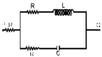
166010
A voltage $V_{P Q}=V_{0} \cos \omega t$ ( where, $V_{0}$ is a real amplitude) is applied between the points $P$ and $Q$ in the network shown in the figure. The values of capacitance and inductance are
$c=\frac{1}{\omega R \sqrt{3}} \text { and } L=\frac{R \sqrt{3}}{\omega}$
Then, the total impedance between $P$ and $Q$ is