356914
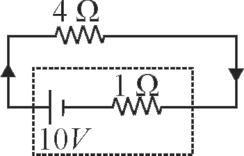
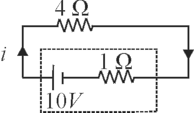
The terminal voltage of the battery, whose emf is \(10\,V\) and internal resistance \({1 \Omega}\), when connected through an external resistance of \({4 \Omega}\) as shown in the figure is:
1 \({4 V}\)
2 \({6 V}\)
3 \({8 V}\)
4 \({10 V}\)
Explanation:
Let \({i}\) be the current through the circuit Current in circuit \(i = \frac{{10}}{{4 + 1}} = 2\;A{\rm{ }}\) Terminal voltage \( = \varepsilon - iR\) \( = 10 - 2 \times 1 = 8\;V\)
NEET - 2024
PHXII03:CURRENT ELECTRICITY
356915
The direction of current inside a cell is
1 \(( - )ve\) pole to \(( + )ve\) pole during discharging
2 \(( + )ve\) pole to \(( - )ve\) pole during discharging
3 Always \(( - )ve\) pole to \(( + )ve\) pole
4 Always flows from \(( + )ve\) pole to \(( - )ve\) pole
Explanation:
During discharging of a battery current flows from \(( + )ve\) to \(( - )ve\) outside the battery and \(( - )ve\) to \(( + )ve\) inside the battery.
PHXII03:CURRENT ELECTRICITY
356916
A cell of emf 4 \(V\) and internal resistance \({0.2 \Omega}\) is connected with the resistance of \({1.8 \Omega}\). The voltage across the cell terminal will be
1 6.3 \(V\)
2 2.4 \(V\)
3 3.8 \(V\)
4 3.6 \(V\)
Explanation:
\({ V=\varepsilon-I r}\) \(\begin{array}{ll}\because & I=\dfrac{\varepsilon}{(R+r)}=\dfrac{4}{2}=2 {~A} \\\therefore & V=4-I r=4-2(0.2) \\& V=4-0.4=3.6 {~V}\end{array}\). So correct option is (4)
PHXII03:CURRENT ELECTRICITY
356917
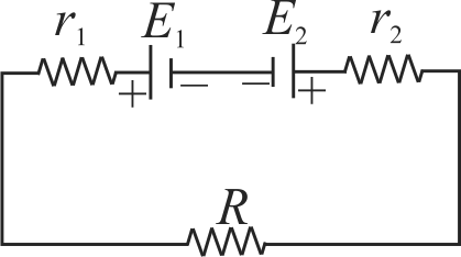
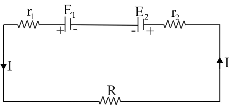
Two cells of emf \({E_1}\,{\rm{and}}\,{E_2}\) are joined in opposition (such that \({E_1}\, > {E_2}\)). If \({r_1}\,{\rm{and}}\,{r_2}\) be the internal resistance and \(R\) be the external resistance, then the terminal potential difference is
356914
The terminal voltage of the battery, whose emf is \(10\,V\) and internal resistance \({1 \Omega}\), when connected through an external resistance of \({4 \Omega}\) as shown in the figure is:
1 \({4 V}\)
2 \({6 V}\)
3 \({8 V}\)
4 \({10 V}\)
Explanation:
Let \({i}\) be the current through the circuit Current in circuit \(i = \frac{{10}}{{4 + 1}} = 2\;A{\rm{ }}\) Terminal voltage \( = \varepsilon - iR\) \( = 10 - 2 \times 1 = 8\;V\)
NEET - 2024
PHXII03:CURRENT ELECTRICITY
356915
The direction of current inside a cell is
1 \(( - )ve\) pole to \(( + )ve\) pole during discharging
2 \(( + )ve\) pole to \(( - )ve\) pole during discharging
3 Always \(( - )ve\) pole to \(( + )ve\) pole
4 Always flows from \(( + )ve\) pole to \(( - )ve\) pole
Explanation:
During discharging of a battery current flows from \(( + )ve\) to \(( - )ve\) outside the battery and \(( - )ve\) to \(( + )ve\) inside the battery.
PHXII03:CURRENT ELECTRICITY
356916
A cell of emf 4 \(V\) and internal resistance \({0.2 \Omega}\) is connected with the resistance of \({1.8 \Omega}\). The voltage across the cell terminal will be
1 6.3 \(V\)
2 2.4 \(V\)
3 3.8 \(V\)
4 3.6 \(V\)
Explanation:
\({ V=\varepsilon-I r}\) \(\begin{array}{ll}\because & I=\dfrac{\varepsilon}{(R+r)}=\dfrac{4}{2}=2 {~A} \\\therefore & V=4-I r=4-2(0.2) \\& V=4-0.4=3.6 {~V}\end{array}\). So correct option is (4)
PHXII03:CURRENT ELECTRICITY
356917
Two cells of emf \({E_1}\,{\rm{and}}\,{E_2}\) are joined in opposition (such that \({E_1}\, > {E_2}\)). If \({r_1}\,{\rm{and}}\,{r_2}\) be the internal resistance and \(R\) be the external resistance, then the terminal potential difference is